Crimpdeq

Meet Crimpdeq, a portable digital force sensor for climbers, coaches, and therapists who want to measure and train finger strength, pulling power, and endurance. It is inspired by the Tindeq Progressor and is compatible with both the Tindeq and Frez apps.
Specs
- Rechargeable battery with USB-C charging
- Communicates via Bluetooth Low Energy (BLE)
- Open-source firmware written in Rust
- Open-source PCB design
- Open-source 3D-printable case design
- Automatic sleep when inactive
- Compatible with the Tindeq Progressor app (Android | iOS)
- Compatible with the Frez app (formerly ClimbHarder) (Android | iOS)
- Sampling rate: 80 Hz
- Full-scale design load: 1500 N (~150 kg)
- Precision:
- 0.05 kg between 0 and 99 kg
- 0.1 kg between 100 and 150 kg
- Operating temperature: 0 to 40 C
- Dimensions: 80 x 90 x 35 mm
- Uses the Tindeq Progressor API
⚠️ Warning: Some values depend on the load cell used in this project. If you use a different load cell, those values may change.
Book Contents
This book is a practical guide to understanding Crimpdeq and building your own. It covers assembly, calibration, firmware internals, and the PCB and 3D-printable case design.
⚠️ Note: If you want to reproduce this project, feel free to reach out by email (sergio.gasquez@gmail.com), X (formerly Twitter), or Bluesky.
Build Your Crimpdeq
This chapter presents the Crimpdeq models you can build.
Choose the one that matches your tools, budget, and how much assembly work you want to do.
Crimpdeq PCB Build
This model uses a custom PCB and a custom 3D-printed case.
It is the cleanest and easiest version to assemble, and the final result is more compact and polished. The assembly guide covers both PCB V1 and PCB V2, including their wiring differences.
Follow the Crimpdeq Assembly guide to build this model.
Prototype
This model reuses a crane scale case and combines off-the-shelf modules (ESP32-C3 Rust Board + HX711).
It requires more soldering and manual assembly, but it can be cheaper because it does not require manufacturing a custom PCB or 3D-printed case.
Follow the Prototype Assembly guide to build this model.
Crimpdeq Assembly
This chapter shows how to assemble a Crimpdeq using the custom PCB and 3D-printed case.
Most assembly steps are the same for PCB V1 and PCB V2. The main difference is the external wiring pad layout, especially the battery/switch wiring.
1. Gather Parts and Tools
Parts
- Crimpdeq PCB
- See the PCB manufacturing guide if you need to order one.
- Crimpdeq 3D-printed case that matches your PCB revision
- WH-C07 load cell, or a compatible load cell with similar dimensions
- You can salvage one from a crane scale (Amazon alternative) or buy it separately.
- 3.7 V, 2000 mAh LiPo battery
- KCD11 two-terminal switch
- Insulated hookup wire and heat-shrink tubing
- 4 × M2.5 screws
Tools
- Soldering iron and solder
- Wire cutters and strippers
- Multimeter
2. Identify Your PCB Layout
Before soldering, identify which PCB layout you have and follow the matching wiring table.
| PCB V1 | PCB V2 |
|---|---|
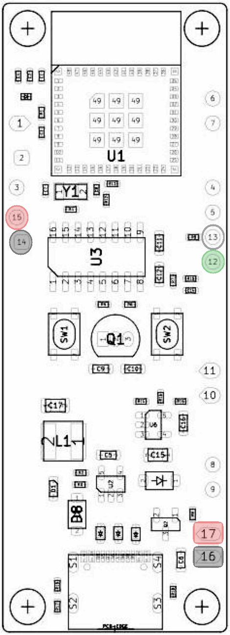 | 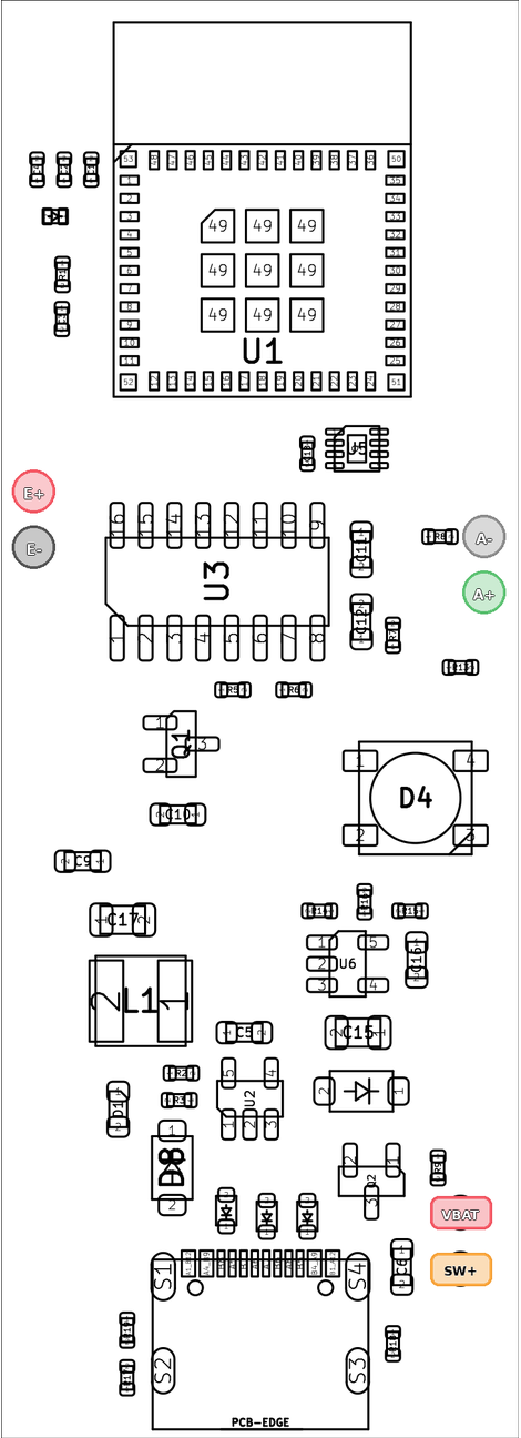 |
The load cell uses numbered pads 12–15; the battery uses 16 and 17. | The load-cell and power pads are labeled E+, E-, A-, A+, VBAT, and SW+. |
The assembly photos in this chapter show a V1 PCB. Use the table below—not the wire positions in the photos—to connect a V2 PCB.
3. Solder the Connections
⚠️ Battery safety: Keep USB power disconnected while wiring. Prevent the battery leads from touching each other, and insulate every splice and switch terminal with heat-shrink tubing. Complete the unpowered checks below before connecting either battery lead.
Load cell
| Function | Typical wire color | PCB V1 pad | PCB V2 pad |
|---|---|---|---|
| Excitation positive | Red | E+ (15) | E+ |
| Excitation negative | Black | E- (14) | E- |
| Signal positive | Green or blue | S+ (12) | A+ |
| Signal negative | White | S- (13) | A- |
⚠️ Note: Wire colors are not guaranteed. Confirm the labels or documentation for your load cell before soldering.
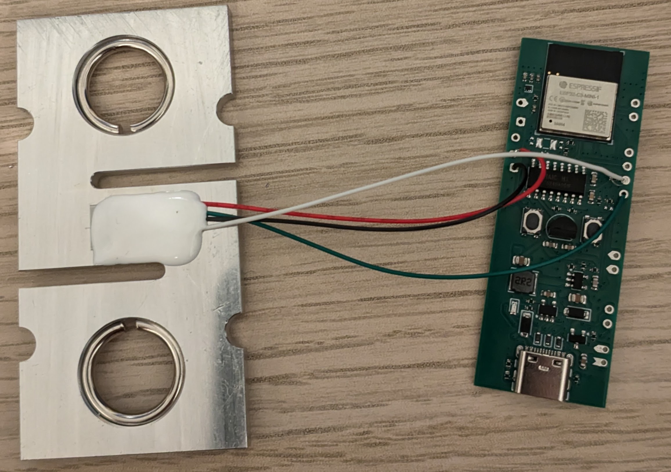
Reference photo of the load cell wires after soldering them to a V1 PCB:
Battery and switch
Before soldering the switch terminals, feed both switch wires from inside the case through the switch opening and slide heat-shrink tubing onto them. Solder the switch outside the case; you will press it into the opening later. Do not attach the switch before feeding the wires through the opening.
Leave both battery leads disconnected until instructed to connect them below.
PCB V1
- Solder a wire from
B+ (17)to either switch terminal. - Leave the other switch terminal available for the battery positive wire.
The completed circuit will place the switch in series with the positive lead: battery + → switch → B+ (17).
PCB V2
- Solder a wire from
SW+to either switch terminal. - Connect the other switch terminal to
VBATwith a short jumper. - Plan the shared
E-connection for the load-cell and battery negative wires.- If both wires do not fit cleanly in the pad, make a short insulated pigtail from
E-with one branch for each wire.
- If both wires do not fit cleanly in the pad, make a short insulated pigtail from
The completed connections will be:
battery + → VBATVBAT → switch → SW+battery − → E-
⚠️ Important V2 difference: Unlike V1, V2 keeps
VBATconnected to the battery while the switch is off. This allows the battery to charge while the device is off. Do not place the switch between the battery andVBAT.
Check before connecting the battery
With both battery leads still disconnected, use a multimeter in continuity or resistance mode to check that:
- Battery positive is not shorted to ground (
B+toB-on V1, orVBATtoE-on V2). - Each load-cell wire reaches the correct pad for your PCB revision.
- The switch opens and closes the positive path.
- On V1, check between the free switch terminal and
B+. - On V2, check between
VBATandSW+.
- On V1, check between the free switch terminal and
Resolve any unexpected short or open connection before proceeding.
Connect the battery
- PCB V1: connect battery positive (red) to the free switch terminal, then connect battery negative (black) to
B- (16). - PCB V2: connect battery negative (black) to the shared
E-connection, then connect battery positive (red) toVBAT.
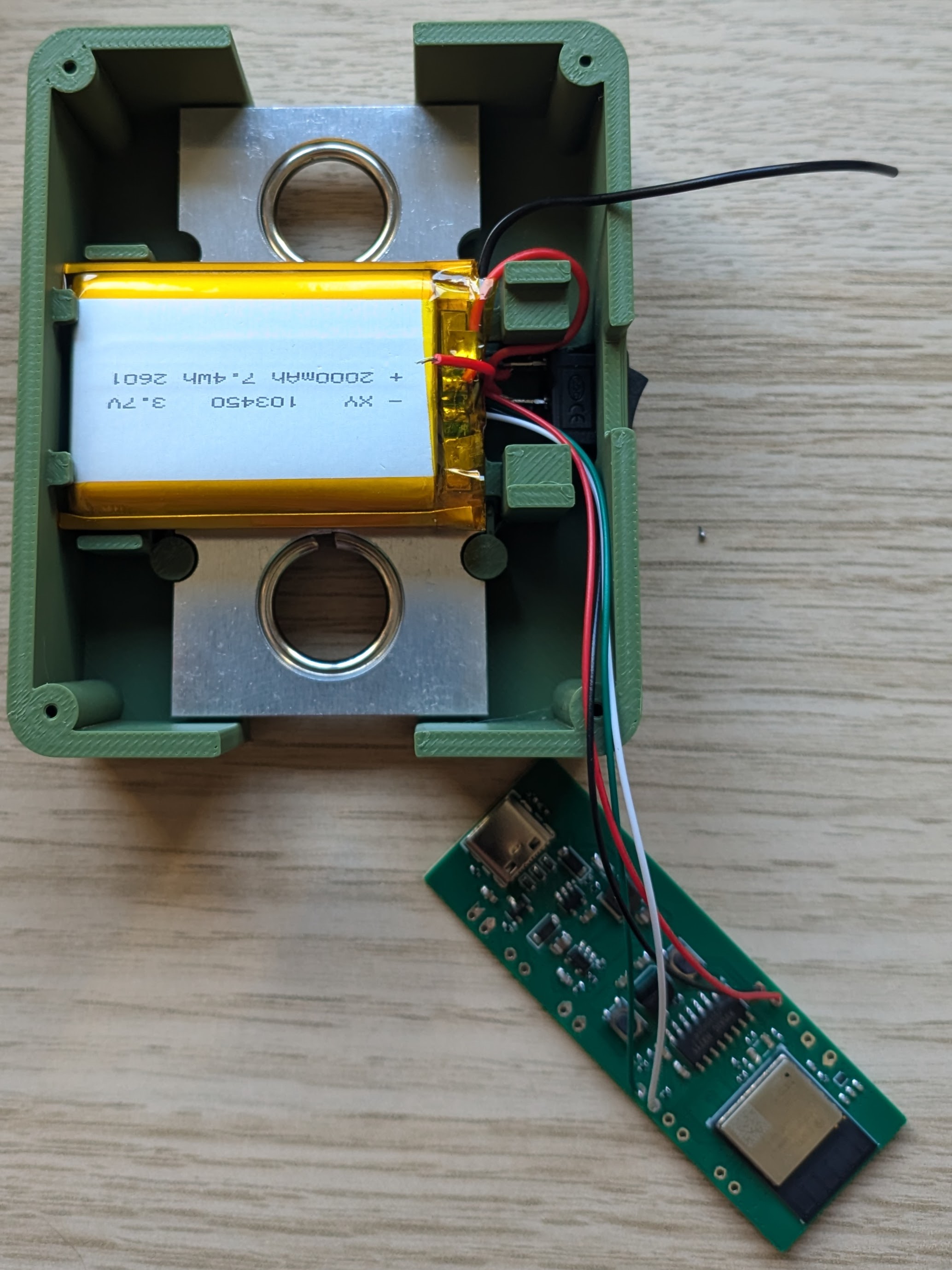
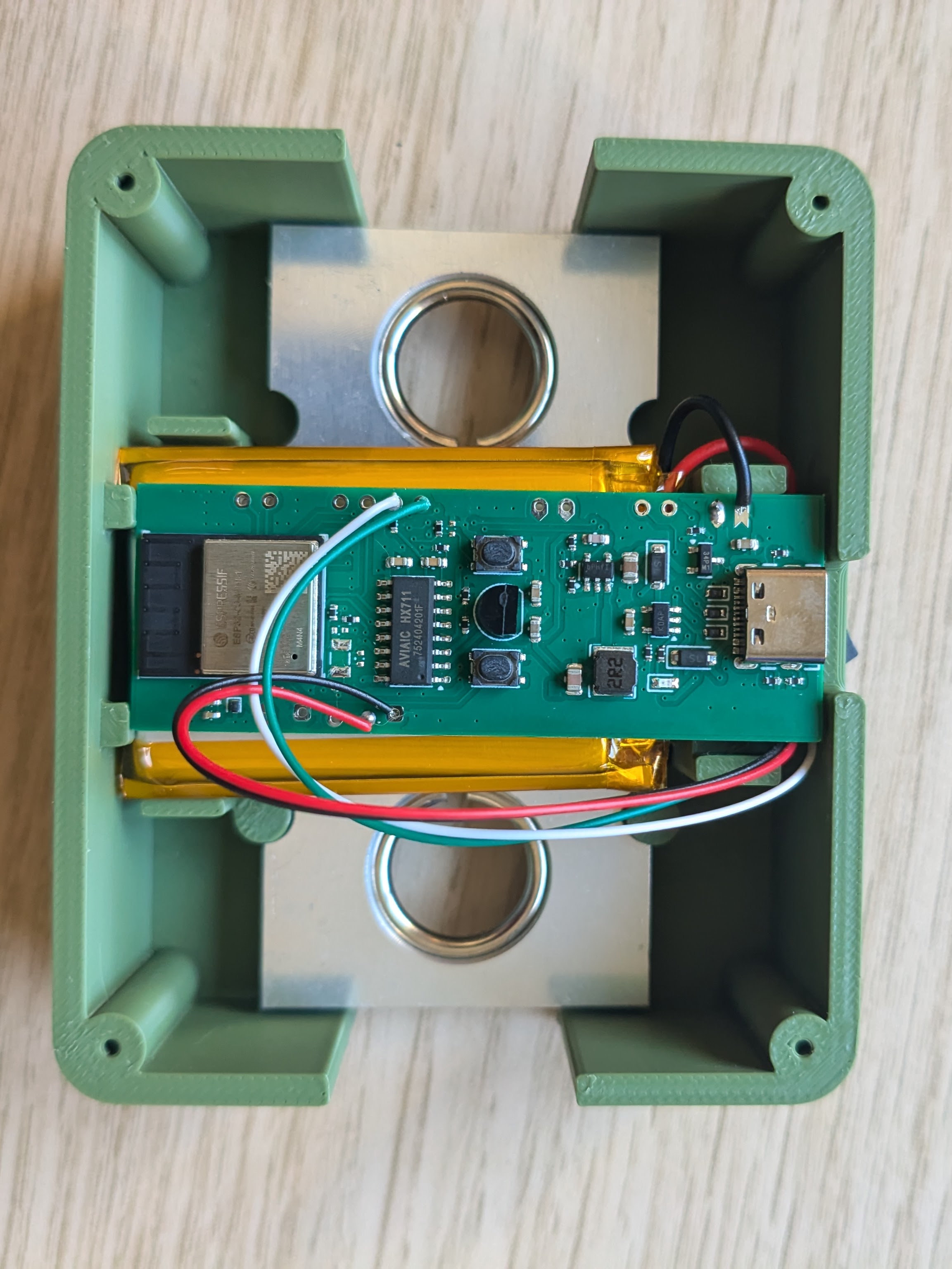
4. Install Everything in the Case
- Place the load cell in its position in the 3D-printed case.
- Route the load cell wires so they are not pinched by the PCB or the lid.
- Place the battery in the battery compartment.
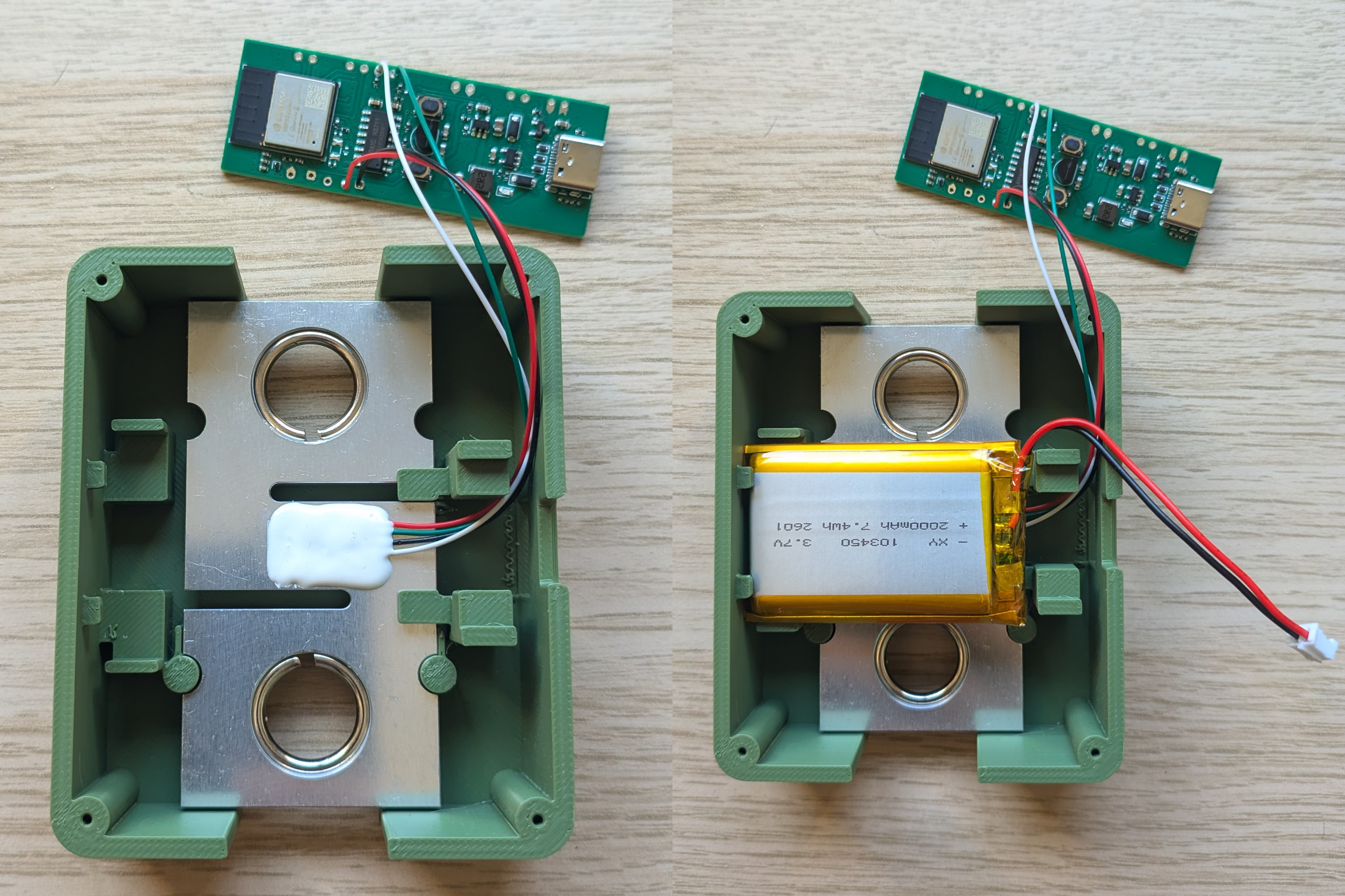
- Position the PCB in the case.
- Tuck the wires neatly around it so nothing sits under the board.
- Insert the KCD11 switch into the switch opening.
5. Verify the Powered Wiring
With USB still disconnected, use the multimeter in DC voltage mode to confirm the polarity and switch behavior:
- PCB V1: place the black probe on
B-and the red probe onB+. The meter should show battery voltage only while the switch is on. - PCB V2: place the black probe on
E-. With the red probe, confirm thatVBATalways shows battery voltage andSW+shows battery voltage only while the switch is on.
Turn the switch off before closing the case.
6. Close the Case
- Place the lid on the main enclosure.
- Fasten it with the 4 × M2.5 screws.
7. Next Steps
- Flash the firmware (see Firmware).
- Calibrate the device (see Calibration).
PCB Design
The PCB design is maintained in the crimpdeq-pcb repository and was created with KiCad.
It is a two-layer board derived from the ESP32-C3-DevKit-RUST-1. It removes unused sensors from the original design and keeps the components needed by Crimpdeq.
Revision 2 (Current)
Revision 2 adds clearly labeled external wiring pads, a power path that supports charging while switched off, a battery gauge, and an RGB LED. Its battery and switch wiring differs from Revision 1; follow the assembly guide.
Revision 1
Revision 1 has been tested and works as expected. Its external connections use numbered pads, as shown below.
The PCB was sponsored by PCBWay. Working with them was fast and easy, and the resulting boards are high quality.

You can find the schematic, layout, and production files for the current revision in the latest GitHub release. Older revisions are available from the release archive.
How to Manufacture
There are two ways to order this PCB:
- Using the PCBWay Project page — recommended, since it already includes the latest uploaded production files.
- Placing your own PCBWay order using the production files from the repository releases.
Using PCBWay Projects
-
Open the PCBWay Project page using the button below.

-
Confirm that the revision shown on the project page is the one you want to build.
-
On the right panel, select PCB+Assembly and click Add to Cart.
-
Enter the desired quantity and click Calculate.
⚠️ Note: PCBWay shows two quantity fields. One is the number of PCBs to manufacture, and the other is the number of boards to assemble with components. The minimum PCB quantity is usually 5.
-
Choose your shipping country and shipping method.
-
Click Save to Cart to continue with checkout.
Placing Your Own Order on PCBWay
-
Download the production files from the latest GitHub release.
-
Use the included files when creating your PCBWay order:
gerber.zip: PCB fabrication filesbom.csv: bill of materials for assemblypositions.csv: component placement file for assembly
-
Submit the order and wait for the manufacturer review.
- The manufacturer may contact you with questions about substitutions, assembly notes, or file interpretation.
⚠️ Note: If the manufacturer contacts you with questions or suggestions and you are unsure how to answer, feel free to email me at sergio.gasquez@gmail.com.
3D-Printed Case
The case design is maintained in the crimpdeq-case repository and was created with OpenSCAD.
It consists of two parts (main body and lid) and includes mounting points for the load cell, battery, PCB, and switch.
Download the printable files from the repository releases and choose a case version that matches your PCB revision. Print both parts before assembly.
Prototype Assembly
This chapter explains how to build your own Crimpdeq prototype.
1. Required Materials
- ESP32-C3-DevKit-RUST-1
- Other ESP32 boards can work, but you must provide your own battery charging solution.
- Battery Holder
- 18650 Battery
- Other batteries may also work if they can power the device.
- Crane Scale or Amazon alternative
- Other crane scales may also work.
- HX711 module:
- [Optional] Resistors:
- 1× 33 kΩ resistor
- 1× 10 kΩ resistor
2. Disassemble the Crane Scale
- Desolder the battery connections.
- Desolder the four load cell wires (
E-,S-,S+, andE+) from the PCB. - Unscrew and remove the PCB and display.
3. Soldering
-
Modify the HX711 module:
- Set the sample rate to 80 Hz. Most HX711 modules ship with
RATEtied toGND, which sets 10 Hz. To switch to 80 Hz:- Cut the PCB trace to the
RATEpin.- Carefully scratch the trace with a knife.
- Verify with a multimeter that
GNDandRATEare no longer connected.- Take care not to damage adjacent traces.
- Solder the
RATEpin to theDVDDpin. - Verify with a multimeter.
- Cut the PCB trace to the
- [Optional] Improve measurements at 3.3 V. Most HX711 modules are configured for 5 V operation:
- Solder a 20 kΩ to 27 kΩ resistor in parallel with
R1(highlighted in the image):
- For more information, see this blog post.
- This step is optional but improves measurement quality.
- Solder a 20 kΩ to 27 kΩ resistor in parallel with
- Set the sample rate to 80 Hz. Most HX711 modules ship with
-
Connect the load cell to the HX711:
- Solder the four wires from the crane scale to the HX711. Typical color mapping:
HX711 Pin Load Cell Pin Description E+ E+ (Red) Excitation positive (to load cell) E- E- (Black) Excitation negative (to load cell) S+ S+ (Green or blue) Signal positive (from load cell) S- S- (White) Signal negative (from load cell) ⚠️ Note: On some HX711 modules,
S+/S-are labeledA+/A-. Wire colors are not guaranteed, so confirm your load cell’s wiring before soldering. -
Connect the HX711 to the ESP32-C3-DevKit-RUST-1:
| HX711 Pin | ESP32-C3 Pin | Description |
|---|---|---|
| VCC | 3.3V | Power supply (3.3V) |
| GND | GND | Ground |
| DT (Data) | GPIO4 | Data output from HX711 |
| SCK (Clock) | GPIO5 | Clock signal for communication |
- [Optional] Solder the voltage divider:
- Solder one end of the 33 kOhm resistor to
B+on the ESP32-C3-DevKit-RUST-1. - Join the other end of the 33 kOhm resistor with one end of the 10 kOhm resistor, then connect that junction to
GPIO1. - Solder the remaining end of the 10 kOhm resistor to
GND.
- The firmware expects the battery sense on
GPIO1by default. Adjust the firmware configuration if you wire a different pin.
- Solder one end of the 33 kOhm resistor to
- Verify all connections with a multimeter.
4. Adapt the Scale Case
- Create space for the USB connector.
- For example: mark the opening with a pen, then carefully heat a knife and melt the plastic.
- Install the battery holder:
- Glue the battery holder with silicone. Leave the original battery lid opening free so you can route the two battery wires through it.
- Solder the positive wire (red) from the battery holder to a switch/button for power. Then solder the other switch/button pin to
B+on the ESP32-C3-DevKit-RUST-1. - Solder the negative wire (black) from the battery holder to
B-on the ESP32-C3-DevKit-RUST-1.
- Close the case after confirming all components are secure.
Firmware & Flashing
The Crimpdeq firmware is written in async Rust (no_std) using esp-hal and a small set of supporting crates.
This section explains how to flash the firmware to your device and, optionally, how the code is organized.
Choose a Flashing Method
There are two supported ways to flash the firmware:
1. Web Tools
- No local setup required
- Fastest way to install the latest release
- Best if you do not plan to modify the firmware
2. Local Setup
- Requires installing Rust and
probe-rs - Lets you build from source and modify the code
- Better for development and debugging
Firmware Internals
If you want to understand or modify the firmware, see the Firmware Details chapter.
If you only want a working device, you can flash the firmware and continue to Calibration.
Flash with Web Tools
This chapter covers how to flash your device with a pre-built binary.
-
Connect the device with a USB-C cable.
-
Download a
.binfrom the latest GitHub release:- If this is the first time you are flashing Crimpdeq firmware to your device, download
crimpdeq-merged.bin. - If you are updating firmware on a device that is already flashed, download
crimpdeq.bin.
- If this is the first time you are flashing Crimpdeq firmware to your device, download
-
Choose a web flasher. Use either:
- esp.huhn.me
- See this blog post for extra details.
- Adafruit ESPTool
- esp.huhn.me
-
Click
Connectand select the serial port for your ESP board.- In Adafruit ESPTool, the port often appears as
USB/JTAG serial debug unit....
- In Adafruit ESPTool, the port often appears as
-
Click
Eraseonly if this is the first time you are flashing this device.⚠️ Note: Erasing the device also erases stored calibration values. Skip this if the device was already programmed and calibrated.
-
Upload your
.bin:- If you are using
crimpdeq-merged.bin-> address0x0 - If you are using
crimpdeq.bin-> address0x10000
- If you are using
-
Click
Program.
Flash with Local Setup
This chapter covers how to compile and flash the Crimpdeq firmware to your device.
Prerequisites
To build and upload the firmware, install:
- Rust
- The
stabletoolchain with the ESP32-C3 target:rustup toolchain install stable --component rust-src --target riscv32imc-unknown-none-elf probe-rs, see installation instructions⚠️ Note: Depending on your OS, you may need extra setup steps:
- Linux: set up udev rules for your debug probe or USB-serial device (see the
probe-rsudev guide). - Windows/macOS: ensure the correct USB drivers are installed and select the appropriate serial port in your tooling.
- Linux: set up udev rules for your debug probe or USB-serial device (see the
How to Build the Firmware
To build the firmware, run:
cargo build --release
This compiles the firmware only. To build and flash the device, see Build and Flash your Device.
How to Flash Your Crimpdeq
Erase Device Memory
If this board was previously used for other projects, erase its flash once:
probe-rs erase
⚠️ Note: Erasing is only needed once. Avoid erasing routinely, or you will lose your calibration values.
Build and Flash Your Device
With a custom runner configured in .cargo/config.toml, you can build, flash, and open a serial monitor with:
cargo run --release
This opens a serial monitor, allowing you to view log messages in real time.
To modify the log level, update the DEFMT_LOG value in .cargo/config.toml or set it when running the command:
DEFMT_LOG=debug cargo run --release
⚠️ Note: If your DevKit does not include USB-Serial-JTAG, flash over UART by updating the custom runner in
.cargo/config.tomlto useespflashinstead ofprobe-rs.
Configuring Environment Variables
If you need to change DEVICE_ID, DEVICE_NAME, or DEVICE_VERSION_NUMBER, update their values in .cargo/config.toml.
After making changes, rebuild and flash the device for the new values to take effect.
Firmware Internals
Code Structure
hx711
This module implements load cell support. It is an async version of the loadcell crate with project-specific changes.
ble
This module implements the Bluetooth Low Energy (BLE) functionality:
- Defines the GATT server and services
- Handles advertising and connections
- Defines the Progressor service with data point and control point characteristics
progressor
The progressor module implements the Tindeq API used for BLE communication between the ESP32-C3 and a smartphone.
Main Tasks
The main.rs file defines several asynchronous tasks that run concurrently:
measurement_task:- Initializes the load cell.
- Handles taring and reads measurements from the sensor.
ble_task:- Long-running background task required alongside other BLE tasks.
gatt_events_task:- Processes GATT events such as control-point writes.
data_processing_task:- Handles sending notifications with data points.
battery_voltage_task:- Periodically reads the battery voltage.
deep_sleep_task:- Monitors inactivity; after a timeout, the device enters deep sleep.
Communication between tasks occurs via a Channel.
Calibration
This guide explains how to calibrate Crimpdeq for accurate measurements.
You can calibrate in two ways: with the Crimpdeq app or nRF Connect.
The Crimpdeq app is recommended because it is simpler and gives visual feedback.
⚠️ Note: The device ships with a default calibration. Test it first in the Frez or Tindeq app. If accuracy is already good enough for your load cell, you can skip this chapter.
Calibrate with Crimpdeq App
Prerequisites
- Crimpdeq app on your platform:
- Web version (no installation): Crimpdeq web app
- Not all browsers support WebBluetooth. Check browser compatibility.
- Native builds from the latest release: crimpdeq-app/releases/latest
- Android:
crimpdeq-app-v<x.y.z>.apk - macOS:
crimpdeq-app-v<x.y.z>-macos.zip - Windows:
crimpdeq-app-v<x.y.z>-windows.zip - Linux:
crimpdeq-app-v<x.y.z>-linux.zip
- Android:
- Web version (no installation): Crimpdeq web app
- A stable mounting point so the device hangs freely and remains still
- At least one known weight (ideally near your typical maximum load)
Calibration Steps
-
Connect to your Crimpdeq
- Launch the Crimpdeq app and grant permission to access device location (required for Bluetooth).
- Tap Scan to pair with your device.
- Once connected, the app shows device info (firmware version, battery, and current calibration).
-
Add calibration points
- Open the Calibration tab.
- For each point:
- Hang the corresponding load on the device (or leave it empty for zero).
- Enter the weight value in the app and tap Add Calibration Point.
- Recommended: Add at least 2 points—zero (nothing hanging) and full scale (the maximum weight you expect to measure). The device supports up to 20 calibration points for finer accuracy.
-
Check the result
- After adding at least 2 points, the app displays the current calibration curve. Confirm it matches your expectations.
Adding more calibration points (up to 20) improves measurement accuracy across the full load range.
Calibrate with nRF Connect
Prerequisites
- nRF Connect installed on your platform:
- A stable mounting point so the device hangs freely and remains still
- At least one known weight (ideally near your typical maximum load)
Calibration Steps
- Connect to Crimpdeq with nRF Connect:
- Launch the app and go to the Scanner tab.
- Find your device (for example,
Progressor_7125) and tapConnect. - Once connected, the app will display the device’s services and characteristics.
- Locate the calibration characteristic:
- Expand Unknown Service.
- Find the characteristic with UUID:
7e4e1703-1ea6-40c9-9dcc-13d34ffead57.
- Compute the hex value of your known weight:
- Open the Floating Point to Hex Converter.
- Select
Single-precision(32-bit) floating point. - Enter your known weight in the
Float valuefield (in kilograms unless your device expects grams; see Important Notes). - Click
Convert to hexand save the resultingHex value. Example: 75.3 kg →0x4296999a.
- Zero the device (tare):
- Hang Crimpdeq with no weight attached.
- Send the command
7300000000to the characteristic:- Tap the Up Arrow icon on the characteristic (
7e4e1703-1ea6-40c9-9dcc-13d34ffead57). - Enter the command as shown.
- Tap the Up Arrow icon on the characteristic (
- Perform the calibration:
- Commands and values are hex strings without spaces (letter case does not matter).
- Attach your known weight to Crimpdeq.
- Build the calibration command by prefixing
73to your hex value.- Example: For 75.3 kg (
0x4296999a), send:734296999a.
- Example: For 75.3 kg (
- Send this command to the same characteristic (
7e4e1703-1ea6-40c9-9dcc-13d34ffead57).
- You can add up to 20 calibration points. Repeat this step if you need higher accuracy.
- Verify:
- Remove the weight and reattach it.
- The reported value should be within a small tolerance of the known weight. If not, repeat steps 4-5.
⚠️ Note:
- Units: Some devices expect the calibration value in grams instead of kilograms. If, after calibration, the measured value looks off by a factor of ~100 (e.g., 75.3 kg shows ~0.75), convert your known weight to grams and repeat step 5.
- Use a weight close to the maximum load you expect to measure (while staying within device limits) for best accuracy.
- Ensure the device is stable and stationary when sending commands.
- Perform calibration in a controlled environment (avoid wind, vibration, and temperature swings).
Battery Charging
To charge the device:
- Plug the device into a power source using a USB-C cable.
- Set the power switch for your PCB revision:
- PCB V1: turn the device on.
- PCB V2: leave the device either on or off; V2 supports charging while switched off.
- Check that the red charging LED turns on.
- When the red LED turns off, charging is complete. Unplug the USB-C cable.